

Employing the Balanset-1A System
Getting the Equipment Ready
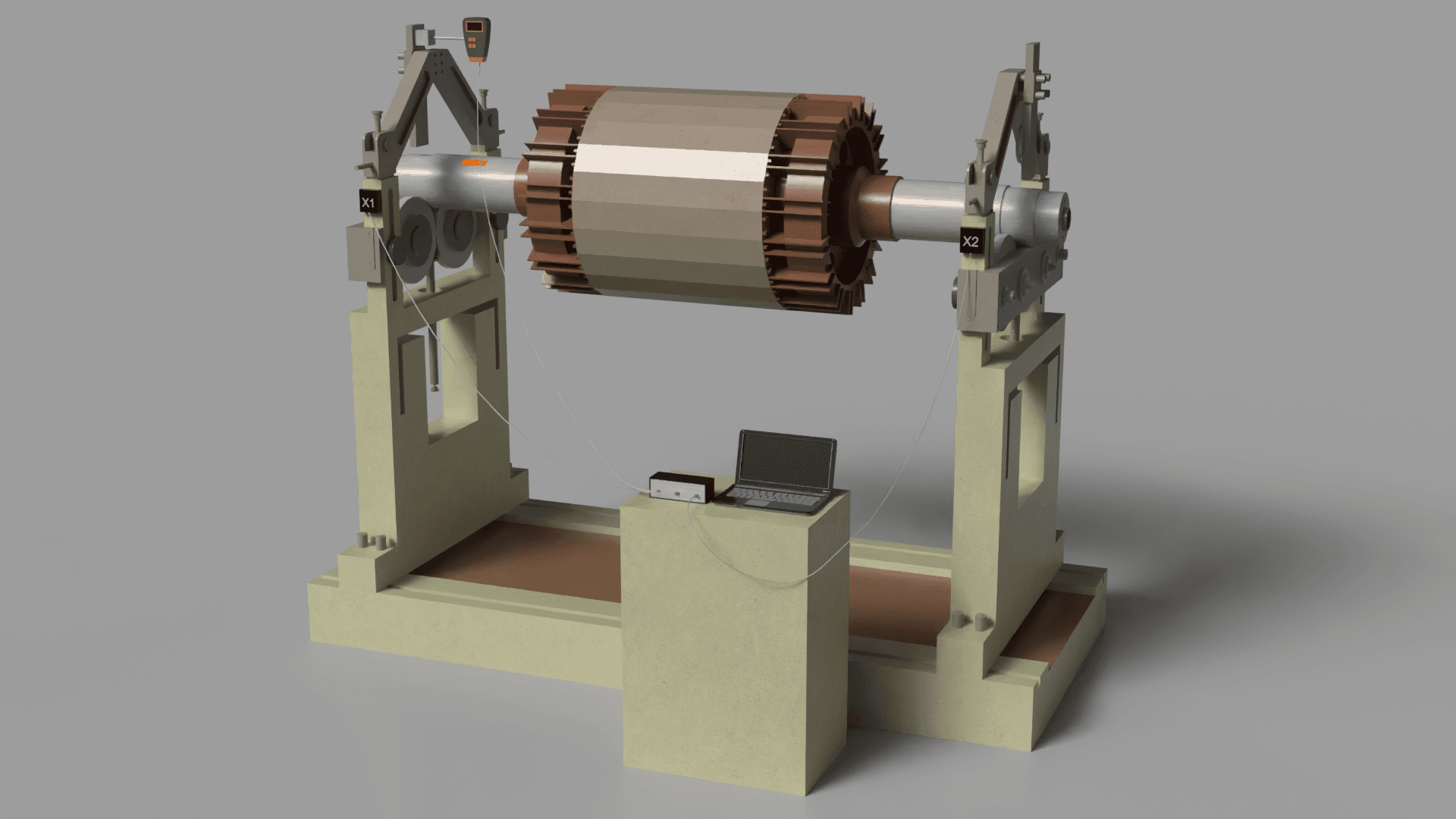
- vibration sensors, optical speed sensor, magnetic base, software package, and included accessories.
- Establish a USB connection between the instrument and the computer, ensuring the software is set up properly.
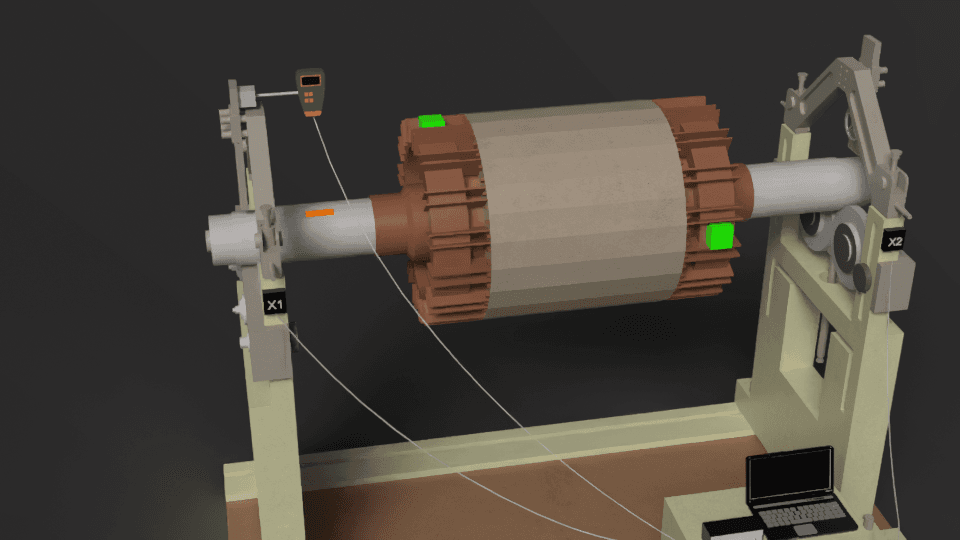
Sensor Installation
- Fix the accelerometers securely to the machine's structure in locations where vibrations are most prominent, ideally near the bearings.
- Position the laser tachometer (phase angle sensor) so that it is aimed at the rotor. Attach reflective tape to the rotor for accurate phase angle reading.
Starting the Program
- Initiate the Balanset program on your computer.
- Select the appropriate balancing mode: single-plane or two-plane, depending on the rotor type and your specific requirements.
Measuring Initial Vibration
- Run the rotor up to its operating speed.
- The software will measure the vibration level, rotational speed, and phase angle. This data establishes the current imbalance condition.
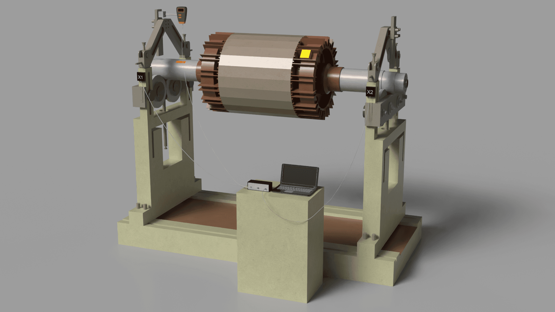
Trial Weight Installation
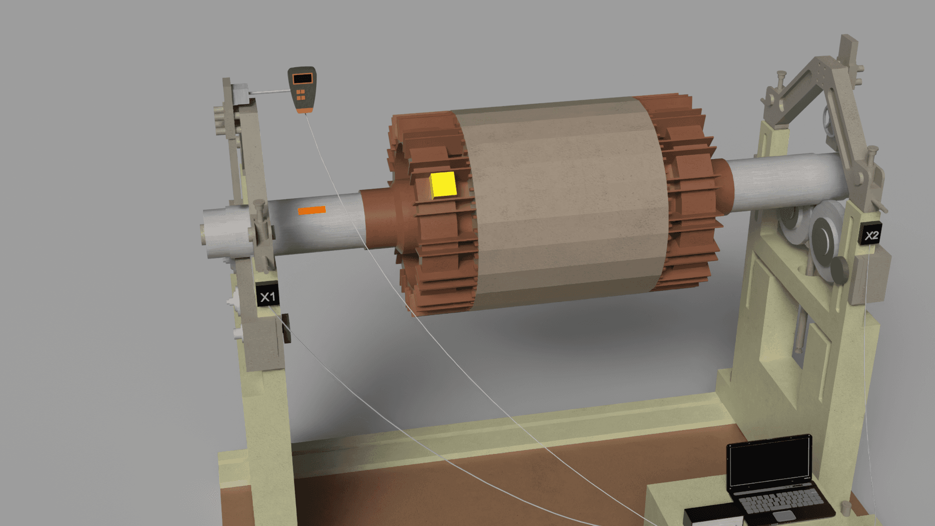
- Stop the rotor and attach a trial weight at a specific location on the rotor. The weight's mass can be specified within the software (e.g., in grams).
- Run the rotor again, allowing the software to measure the effects of the trial weight on vibration and phase.
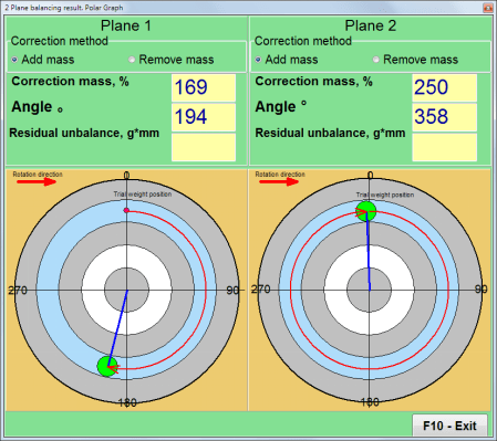
Calculating the Correction Weight
- Based on the measured data, the software automatically calculates the correction weight parameters: mass and installation angle.
- These parameters are displayed on the screen as numerical data and graphs.
Mounting the Compensating Weight
- Attach the computed compensating weight to the rotor as indicated by the software's output.
- Periodic checks can be performed to ensure the balancing procedure is effectively reducing the vibration.
Validation and Conclusion of the Balancing Process
- With the compensating weight attached, operate the rotor and assess the level of any residual vibration.
- If the measured vibration falls within the tolerance defined by ISO 1940, the balancing process is considered successful.
- If the vibration is still outside acceptable limits, reiterate the process and fine-tune the compensating weight.
Generating a Documentation of the Balancing Results
- The program stores the balancing data, allowing you to generate and print a comprehensive report including vibration measurements, corrective weight details, and its angular placement.
Post-Balancing Checklist
- Verify the secure attachment of all balancing weights and measurement sensors.
- Confirm that the rotor spins freely and quietly, without any unusual sounds or vibrations.
- In cases where the rotor is integrated into a more complex system, ensure the correct operation and interaction of all related components.
This process allows for precise imbalance correction, reducing vibration and extending equipment life.
Instagram: https://www.instagram.com/vibromera_ou/ Youtube : https://youtu.be/guA6XJ-ArZM?si=vmkuX7RILzKBl0zL Our website about Balancing tool